One-Stop Global Solar Module Mounting Structure Supplier

Blog

One-Stop Global Solar Module Mounting Structure Supplier

Home

Blog

  • Showcasing Resilient PV Solutions for the Middle East at WFES 2026
    Jan 07, 2026
    Solar First Group is excited to connect with industry leaders and partners at the World Future Energy Exhibition (WFES) 2026 in Abu Dhabi! Join us from January 13–15 at Booth 5008, ADNEC, where we will showcase our tailored photovoltaic solutions designed for the Middle East’s unique climate and energy landscape. As the region accelerates its green transition, we are proud to present our high‑performance, durable product lines—engineered for high temperatures and strong winds. Our integrated solutions include:▸ Rooftop Mounting System▸ Ground Mounting System▸ Solar Tracking System▸ BIPV Carport Each solution is designed with a focus on:▸ High environmental adaptability▸ Enhanced structural stability▸ Rapid and efficient installation This exhibition represents a strategic platform to discuss the future of renewable energy and explore collaborations that drive sustainable growth. We invite you to visit our booth, engage with our team, and discover how Solar First Group’s innovation can support your energy projects. 👉 Stay connected with us for more industry insights and updates: LinkedIn: https://www.linkedin.com/feed/update/urn:li:activity:7414549290963927040 facebook: https://www.facebook.com/share/p/1CtpoypanX/ Web: www.esolarfirst.com Let’s shape a greener future together.
  • Turning waste into treasure, harnessing water: the green energy rebirth of a mining lake
    Dec 26, 2025
    🌞 Under the Malaysian sun, a 15.6 MWp solar array floats serenely on the surface of a former tin mining lake, reflecting a tranquil glow that blends technology and nature. 💡 Clean energy is steadily generated from here, providing a continuous source of renewable power to the local grid. This Malaysian floating photovoltaic project, with its floating system provided by Solar First Group, is writing a green chapter of "turning waste into treasure and water into gold." ⚠️ This lake, formed from water stored in a mine pit, possesses abundant solar energy resources, but also presents hidden challenges: Sandy lakebed 🏝️, uneven terrain, and a water depth exceeding 20 meters all make traditional photovoltaic construction difficult. How to build a safe, reliable, and sustainable energy ark on this "extraordinary" body of water has become the key challenge for the project's implementation. 🛠️ Solar First Group provided a practical solution to these challenges: The project team conducted an in-depth assessment of the site conditions, and considering the local warm and arid climate and complex hydrology, ultimately adopted the TGW-03 main-floating system as a response. This solution does not pursue a large single structure, but rather employs an innovative modular design of "rods + floats," breaking down the overall structure into smaller, more manageable components for a robust and sustainable approach. Ample ventilation space reserved beneath the photovoltaic panels acts like a natural heat dissipation system for the modules, helping to reduce temperature and improve power generation efficiency. Its structure possesses excellent resistance to environmental loads and overturning resistance, sufficient to cope with the daily fluctuations of the lake surface. ⚓ To address the challenges of anchoring in areas far from the shoreline and with rugged lakebeds, the team employed: Precast concrete blocks as anchors, combined with a system of anchor ropes made of different materials. This robust anchoring solution, like an arm reaching deep into the lakebed, firmly grips the complex terrain, ensuring the entire photovoltaic array remains accurately positioned and securely stable even in deep water. ✅ In the project team's rigorous comparative testing, the TGW-03 system stood out for its comprehensive performance: The floats are connected using all-plastic bolts, which are corrosion-resistant and easy to maintain. The minimal metal connection points between the rods and floats speed up installation and reduce maintenance costs throughout the entire lifecycle. The entire system has obtained TUV certification, and its safety and reliability have withstood international standards. 🌟 When the plan became a reality, the 15.6MWp floating photovoltaic power station was officially completed: The former mining lake has now become a "sunny body of water" carrying green energy. After the project is put into operation, it will generate millions of kilowatt-hours of clean electricity annually, effectively reducing carbon emissions by thousands of tons. It not only provides Malaysia with tangible clean energy but also gives this land new ecological significance. 🚀 What we are witnessing is not only the successful implementation of a floating solar power project, but also Solar First Group's practice of using scenario-based solutions to help develop green power in areas with limited land resources. In the future, such stories of "navigating water" will unfold in more waterways, unfolding a broader blue landscape for global energy transition and ecological synergy. → Jump to LinkedIn 🔗https://www.linkedin.com/feed/update/urn:li:activity:7389495861300371456 → Jump to Facebook 🔗https://www.facebook.com/share/v/17bahAbwZ3/  
  • Why Are Larger PV Modules More Fragile?—Analyzing the Mechanical Strength Crisis and Industry Concerns
    Dec 17, 2025
    Lead-in As module sizes increase, material usage has not risen but instead decreased, leading to high breakage rates in projects. How did this happen, and what hidden information lies behind it?   Table of Contents:Chapter 1: A Startling RevelationChapter 2: Fragile GlassChapter 3: Single TestingChapter 4: Path to Solutions   Chapter 1: A Startling Revelation On October 20, 2025, the renewable energy podcast channel SunCast posted on LinkedIn, citing test results from independent third-party Kiwa PVEL, revealing a shocking phenomenon. Kiwa conducted mechanical load tests on a large number of modules this year, with 20% failing under a static pressure of 1800 Pa. In contrast, the failure rate in 2024 was only 7%. ▽ A linkedin post on the SunCast podcast   This post quickly gained traction on LinkedIn, sparking debates in the comments section over the validity of the 20% failure rate. However, as more third-party institutions joined the discussion, it became clear that high module breakage rates are widely recognized in the industry. ▽ Mechanical load testing at Kiwa Laboratory   In fact, as early as June this year, Kiwa invited 50 module manufacturers for a comprehensive "health check" of their products. Kiwa also innovatively introduced a "Reliability Scorecard" system to help users accurately assess the performance of different manufacturers’ modules.   The tests were strictly conducted in accordance with IEC 61215 standards, covering static load, dynamic load, hail resistance, and electrical performance. The results showed frequent occurrences of glass breakage, frame tearing, junction box damage, and other issues, with an overall high damage rate of 20%. ▽ MSS(Mechanical Stress Sequence) The failure rate of mechanical loads is three times that of previous years   Kiwa’s mechanical load test sequence includes various installation methods, identified by numbers: 400mm mounting holes, ±1800 Pa static pressure test 790mm mounting holes, ±1800 Pa static pressure test Four-corner mounting along the short edge, ±1800 Pa static pressure test Dual-rail four-clamp mounting, ±2400 Pa static pressure test   Clearly, these tests are ranked from highest to lowest in terms of mechanical performance requirements. Kiwa uses this numbering system to track which modules pass which tests, allowing users to indirectly judge the mechanical strength of the modules.   Apart from Kiwa, other third-party institutions worldwide have also noted the widespread issue of module breakage in recent years.   In 2022, FUSC (Federal University of Santa Clara) established a 100 kW experimental site in southern Brazil, equipped with bifacial modules on trackers. Within a year, 83 out of 158 modules developed glass cracks, a breakage rate of 52.5%.   
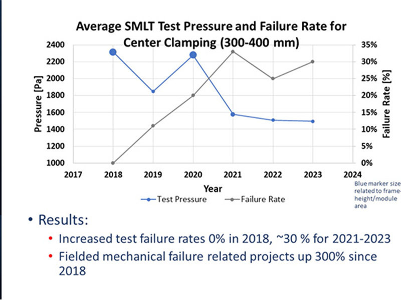
In 2023, CFV Laboratory mentioned in an online exchange that their test data showed module failure rates in 2023 were three times higher than in 2018. Nearly 30% of the modules tested by CFV failed under a test pressure of 1500 Pa. ▽ The pressure resistance of components is decreasing year by year The failure rate of components is increasing year by year   In 2024, DNV published a white paper claiming that in a bifacial module tracker project in the Asia-Pacific region, 15% of the modules’ rear glass broke when wind speeds exceeded 15 m/s.   In February 2025, the IEA PVPS task force released a report on module failure rates, stating that bifacial modules with 2 mm glass could experience rear glass breakage rates of 5–10% within the first two years of installation. ▽ Reports on component damage by PVPS and DNV   In March 2025, IEEE magazine published an article analyzing the current glass breakage rates of bifacial modules, noting that the first five years of a project represent the peak period for module breakage, with rates as high as 17.5%. ▽ The failure rate of components published in the IEEE Photovoltaic Journal   It seems as if, overnight, once-durable modules have become fragile, which is disheartening.   Chapter 2: Fragile Glass Since the trend toward larger modules began in 2020, module sizes have rapidly increased, meaning each module must withstand greater pressure. However, to make matters worse, material usage for larger modules has not increased but decreased: • Glass thickness: reduced from 3.5 mm to 2 mm • Aluminum frame height: reduced from 40 mm to 30 mm • Aluminum frame thickness: reduced from 2 mm to 1.2 mm ▽ As the component size increases, the material usage decreases   While reducing material usage helps decrease the overall weight of modules, speeding up installation, it also raises concerns. According to the National Institute for Occupational Safety and Health (NIOSH), the maximum recommended weight for two-person lifting every five minutes is 33.5 kg.   Clearly, if material usage from the single-glass module era were maintained, many modules would far exceed this weight limit. ▽ NIOSH has strict regulations on artificially lifted weights   Of course, it is widely understood that the primary goal of reducing material usage is cost reduction.   However, cost reduction has inadvertently led to lower quality control. The complexity of producing 2 mm glass is nearing the ceiling of glass manufacturing technology, making quality control far more challenging than for 3.2 mm glass.   To enhance shatter resistance, PV module glass often undergoes thermal and chemical treatments. The strength of the glass largely depends on this treated, reinforced surface layer, which typically accounts for 40% of the glass thickness.   During the 3.2 mm era, manufacturing processes could effectively create this protective layer. However, maintaining the same protective layer thickness in the 2 mm era has become exceptionally difficult. ▽ The protective layer on the surface of the component generally accounts for 40% of the total thickness   Now, the breakage patterns of thick and thin glass in the field have fundamentally changed. Previously, 3.2 mm glass breakage often appeared as "center cracking," making it easier to trace the failure point. In contrast, 2 mm glass failure cracks appear randomly, making it extremely difficult to identify the cause of failure. 
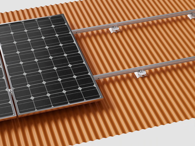
▽ The differences in the production process of component frames also affect the mechanical properties of the components     This complicates the implementation of effective corrective measures when modules are damaged. Even if modules are replaced, similar damage may recur. 
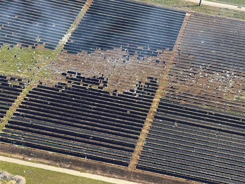
▽ The situation of component glass shattering has changed     Chapter 3: Single Testing Behind the phenomenon of module breakage at project sites, another critical factor cannot be ignored. When module manufacturers specify mechanical performance, they often rely on the test requirements of the IEC 61215 standard. IEC provides a comprehensive testing protocol and specifies a test safety factor: r_m = 1.5.   This cave once wrote a special article titled "Test Loads & Design Loads: How to Match Project Requirements?" The significance of this safety factor is also discussed in the text. The safety factors of glass produced by different processes are also not the same. ▽ The safety factors of different process glasses   This safety factor’s significance varies depending on the glass production process.Due to the inherent randomness and inconsistency in float glass production, the required safety margin is generally higher than for rolled glass. Currently, module manufacturers often opt for cheaper float glass for the rear glass of modules. As shown in the table, the safety factor for annealed float glass ranges from 1.6 to 2.5.   Thus, for material property safety margins, the 1.5 safety factor required by IEC is clearly insufficient.   But this is not the most alarming issue.   When designing projects, a module compatibility test is often conducted to determine whether a specific module matches the tracker structure. This test applies the project’s required loads to the module based on the actual tracker and module installation method. Passing this test is used to verify that the module meets project requirements.   At first glance, this process seems logical and compliant. However, it overlooks a critical issue: all tests are conducted only once. Whether for small kW-scale projects or large GW-scale projects, the reliability of millions of modules in a power plant hinges on a single sandbag test. ▽ The fate of the entire photovoltaic power station lies in a single component test   It is important to note that even for modules of the same model, structural characteristics can vary due to different production batches. This means each module is unique, and testing a single module cannot comprehensively and accurately reflect the true condition of all modules.   Module load testing is similar to structural testing. In the structural industry, obtaining accurate structural characteristics typically requires extensive repetitive destructive testing (test-to-failure). This approach accumulates reliable data to form a stable sample. ▽ For instance, in POT testing, multiple samples are often required and the failure limit is repeatedly measured   It is worth noting that such destructive testing requires a specific sample size, usually 25–50 modules per sample group. Based on this large sample data, a Weibull probability distribution model can be constructed, and statistical analysis can derive the coefficient of variation. Finally, this coefficient of variation can be used to calculate the safety factor corresponding to material uncertainty. ▽ In statistics, the Weibull distribution is often used to determine the probability of product failure   Chapter 4: Path to Solutions This article focuses on the long-term trend in the PV industry: cost reduction and efficiency improvement. Cost reduction is not limited to modules; under immense cost pressures, other system equipment is also exploring optimal cost-reduction paths. However, when various equipment manufacturers’ "new technologies" are applied at the system level, they inadvertently increase the risk of module breakage.   Common cost-reduction measures for tracker manufacturers include: • Increasing the stow angle from 30° to 60° • Reducing purlin thickness from 2 mm to 1.2 mm • Increasing column spacing from 7 m to 10 m • Switching from windward stowing to leeward stowing 
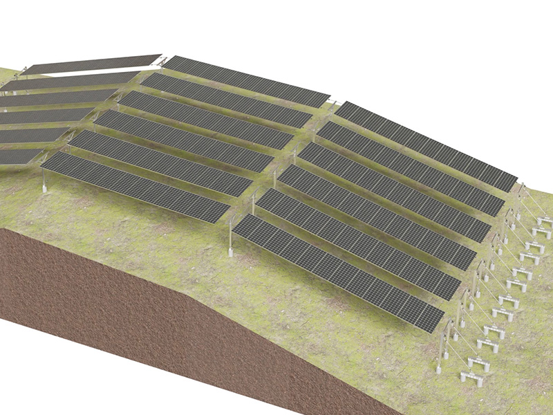
• Adapting to terrain by bending the main shaft and modules to reduce earthwork   Due to industry barriers, collaboration between module and tracker manufacturers is challenging. The result is each party reducing its own costs while shifting the ultimate risk to system users. ▽ Trackers are also adopting various "new technologies" to reduce costs   However, not everyone chooses to "bury their head in the sand." Increasingly, people are actively exploring solutions and proposing various creative ideas. ▽ VDE proposes unbalanced component testing     
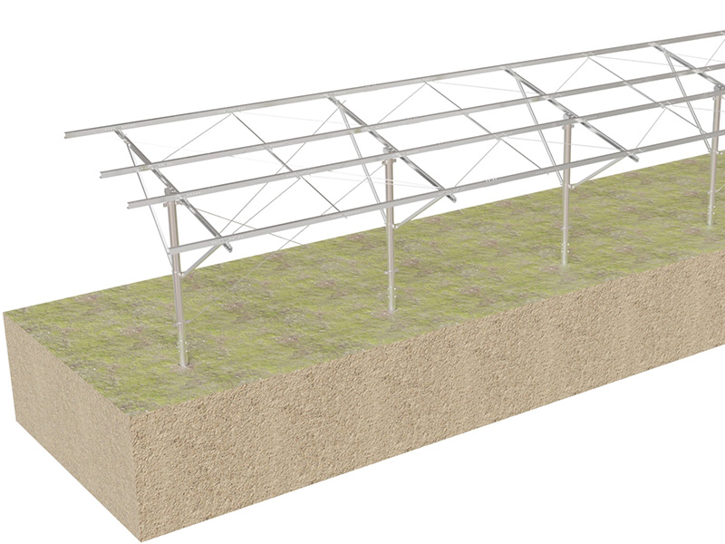
▽ Steel frames can effectively enhance the pressure resistance capacity of components   ▽ The component recycling industry has also quietly emerged   ▽ The general process of component recycling   In 2025, thanks to collective efforts, the cost of PV power generation has reached a historic low. Among various power generation methods, PV has become the undisputed leader in LCOE (Levelized Cost of Electricity). ▽ Photovoltaic power has become the most cost-effective energy source for power generation   This achievement is inseparable from every individual reading this article. Let us work together to break industry barriers, face challenges, and embrace greater opportunities of the era.  
  • From "Facing the Wind" to "Adapting" : The Survival Battle of Photovoltaic Trackers in Extreme Climates
    Dec 11, 2025
    Introduction With the intensification of global warming, the El Nino phenomenon poses increasingly severe challenges to photovoltaic power stations. Many extreme climates that have never occurred before are now influencing our current industry design standards.   Contents Chapter One: Disaster Falls from the Sky Chapter Two: Downstrike Burst Chapter Three: Sudden Increase in Wind Speed Chapter Four: Sudden Change in Wind Direction Chapter Five: Industry Awakening   Chapter One: Disaster Falls from the Sky March 17, 2025, 4 a.m., Texas, USA. The rain outside the window had been drizzling all night. Suddenly, a dazzling thunderclap, like a sharp sword, split the pitch-black sky. Immediately after, the fierce wind, like a wild beast that had broken free from its invisible shackles, roared wildly and rampaged across the ground. The strange crackling sounds that followed gradually broke the tranquility of the small town.   “I was sound asleep when I was suddenly awakened by a loud noise, as if someone was throwing stones at my house. When interviewed, housewife Luna was still shaken. "But the stones came from all directions without any pattern. I was terrified. The horses in the stable were neighing non-stop. That sound was so nerving." ▽ Thunderstorm weather   It wasn't long before dawn broke and the rain stopped. Early in the morning, veteran police officer Frank was driving on Highway 36. In the past, if you turned right at the intersection ahead, you could pass a photovoltaic power station. However, today, the scene before his eyes was chilling. It was a sprawling tracking system. On the originally black-toned components, various holes of different sizes appeared, covering the components like snowflakes. ▽ component was smashed by hail   ▽ The tracker was damaged by hail   In recent years, under the profound influence of the backdrop of global warming, the El Nino phenomenon has become increasingly prominent. Extreme climate events that were once regarded as extremely rare, occurring once in a hundred years or even once in a thousand years, are now frequently making appearances. Traditional design methods often plan ahead to ensure everything is foolproof. However, the occurrence of extreme weather is becoming increasingly irregular and unpredictable. ▽ The tracker was damaged by a tornado   ▽ Fires at photovoltaic power stations occur frequently   Among the numerous extreme weather conditions, there is one that is particularly headache-inducing. Its occurrence is not restricted by time or geography. Like an invisible ghost, it quietly shrouds the area where a crisis may occur, posing a huge threat to photovoltaic power stations.   Chapter Two: Downstrike Burst Thunderstorms are a common meteorological condition, and their occurrence time is usually concentrated in the dusk or at night. During the occurrence of thunderstorms, a large amount of water vapor often accumulates, thus forming a series of "mobile fortresses" with dynamic characteristics that move rapidly on the ground. ▽ Cloud image of thunderstorm weather   These mobile fortresses usually carry many powerful weapons. Once the conditions are right, the fortresses will launch attacks on the ground, causing severe weather phenomena such as heavy rain, hail and strong winds. The most significant impact on photovoltaic trackers is a local climate caused by thunderstorms: downburst. ▽ Downstrike burst   A Downburst, also known as a downburst in English, is a local and small-scale strong downward air current. When this strong air current hits the ground, it will generate destructive linear strong winds. It's like an "air bomb".   The threat of this "air bomb" to photovoltaic trackers mainly comes from two aspects: • a sudden increase in wind speed, with the wind speed rising rapidly within a short period of time; • The wind direction changes suddenly, rapidly within a short period of time.   Chapter Three: Sudden Increase in Wind Speed Friends familiar with photovoltaic trackers should know that when the wind speed exceeds a certain threshold, the tracker will enter the strong wind protection mode. This mode requires the tracker to rotate to the most favorable Angle for itself and stop at this Angle to resist extreme wind speeds.   From here we can find that for the tracker, there are two key wind speed parameters: • Operating wind speed: The minimum wind that triggers the strong wind mode • Extreme wind speed: The maximum wind speed that can be endured at the docking Angle   We can't help but wonder: If the tracker triggers the strong wind mode and the wind speed keeps rising during its rotation, what kind of impact will this have on the structure of the tracker? To discuss this issue, we need to introduce a meteorological term: "sudden increase in wind speed".   ▽ Two types of downburst currents cause a sharp increase in wind speed Microburst (Part 1) Derecho (Part 2) A sudden increase in wind speed, that is, a sudden rise in wind speed within a short period of time, can cause the tracker to be unable to adjust to the Angle of the strong wind in time and may be destroyed by it. This phenomenon is particularly dangerous for single-point drive trackers that adopt the windward docking mode. ▽ A chart of the sharp increase in wind speed in a certain region of the Middle East over the years (15m/s reference, 3s@10m) The wind speed can rise from 15m/s to 33m/s at the fastest within 2 minutes The wind speed soared to 9 meters per second per minute   For single-point drive trackers, 0° is the most unfavorable Angle. The closer to 0°, the worse the stability of the tracker. If the tracker is parked facing the wind but is in the leeward state at this time, after entering the wind protection mode, the tracker needs to rotate in the opposite direction, commonly known as "turning around".   This kind of U-turn tracking will inevitably cause the system to "pass" by 0°. As a result, the tracker will become increasingly unstable as it rotates, and the critical wind speed Ucr will drop further and further. The tracker will gradually enter the "danger zone". If the wind speed rises rapidly at this time, the so-called strong wind protection mode may turn into a "strong wind suicide mode", and the "U-turn" tracking would really mean making a U-turn.   ▽ Single-point drive "dock against the wind" It is impossible to avoid the risks brought by the sudden increase in wind speed   The problem of sudden increase in wind speed is becoming increasingly serious, especially in the Gobi Desert areas. Due to the large temperature difference between day and night, many trackers have suffered varying degrees of damage, mostly related to the sudden increase in wind speed. However, apart from the sudden increase in wind speed, a sudden change in wind direction is another potential threat. ▽ A sudden increase in wind speed caused damage to trackers in a certain area of the Middle East   Chapter Four: Sudden Change in Wind Direction In order to reduce the wind pressure on the modules and enhance their structural stability, traditional photovoltaic tracking systems usually adopt the protection strategy of "docking against the wind", that is, making the modules face the direction of the wind. However, the direction of the wind is not fixed. Under certain extreme weather conditions, such as when a downburst occurs, the wind direction can suddenly change. At this point, the tracker needs to adjust its Angle immediately to prevent damage caused by wind blowing from the back of the component. ▽ A fast motor is adopted to reduce the rotation time of the tracker   The sudden change in wind direction caused by a downburst is characterized by its short duration and high speed, and can even achieve a 180-degree turn within five minutes. This means that the tracker has only five minutes to complete the Angle adjustment. Many tracker manufacturers have recognized this issue and adopted fast motors to increase the rotational speed of the trackers. ▽ The wind direction changed by 180 degrees within five minutes   Unfortunately, most tracker manufacturers adopt a large-angle 60° windward parking strategy. In the worst-case scenario, to turn from 60° east to 60° west, the tracker needs to rotate by a range of 120°. Due to the rapid change in wind direction, even with the use of a fast motor, the time left for the tracker is only five minutes, making it difficult to reach the designated position in time before the wind direction changes.   For this reason, tracker manufacturers have proposed a "full-angle" wind stopover strategy, which means that regardless of how the wind direction changes, the tracker will stop at the maximum Angle position closest to the current tracking Angle.   ▽ Many tracking manufacturers had to give up docking against the wind Change to a "large Angle without wind direction" parking strategy The picture above: PVH The following picture: GameChange   This design breaks the traditional "windward docking" mode, as in this case, the tracker needs to withstand the maximum wind speed at the maximum Angle position on the leeward side. This places extremely high demands on the structural reliability of the entire tracker and also poses a severe challenge to the pressure-bearing capacity of the components.   ▽ The Uplift pressure of components is generally too high when it is sheltered from the wind   Chapter Five: Industry Awakening After the Jordan typhoon disaster in 2018, the first industry awakening of trackers was triggered. A large amount of financial and human resources were invested in the field of wind engineering. The importance of wind engineering has been deeply rooted in people's hearts. Many outstanding engineers have mastered certain knowledge of wind engineering and can even rival senior wind engineering scholars.   Nowadays, the damage caused by extreme weather to photovoltaic power stations has once again sounded the alarm for the tracker industry. A large number of projects are facing situations that have never occurred before. Most extreme weather conditions have not been verified and analyzed in the early stage of design.   Therefore, we can predict that in the future, "atmospheric science" will become an important consideration in tracker design and is bound to drive the second awakening of the tracker industry.   ▽ Atmospheric science is a branch of Earth science   Meanwhile, many third parties have also noticed the severe challenges that extreme weather poses to photovoltaic brackets. For instance, institutions such as VDE and RETC that have performed outstandingly in the field of hail resistance research.   Take the independent non-profit organization RMI in the United States as an example. The organization has published and released three analysis reports on the impact of extreme weather on photovoltaic brackets. The reports are detailed and highly professional, providing important references for the industry.   In addition to the assistance from third-party institutions, tracker manufacturers themselves are also actively exploring methods to obtain real meteorological data. By comparing and analyzing the results with wind tunnel tests, they aim to optimize the design of trackers and enhance their ability to cope with extreme weather. ▽ NREL Flatirons Campus The outdoor wind farm test base of NX and ATI   ▽ The Puertollano Integrated Microgrid Project in Spain Arctech Outdoor Wind Farm Test Base   The photovoltaic tracker industry has stumbled along the way, encountering numerous difficulties and challenges. Extreme weather phenomena are indeed terrifying, but they are not insurmountable. However, when we stand at the crossroads of industry transformation, a greater crisis quietly emerges.   ➡️We look forward to your visit to our website and discussing more technical knowledge about solar energy with you: https://www.esolarfirst.com
  • Engineering a Superior Solar Mounting Solution: The Value of No-Penetration Clamps for Metal Roof Assets
    Dec 10, 2025
    When evaluating solar PV projects for commercial and industrial facilities with metal roofs, the mounting system is not just a component—it’s a critical long-term asset protection decision.Traditional penetrated mounts introduce ongoing liability for leaks, maintenance, and potential compromise of the roof warranty. The alternative? Engineered, non-penetrative clamping systems.Advantage:• Risk Mitigation: Eliminates the single largest point of failure—roof penetrations—preserving the building envelope and reducing lifecycle O&M risks• Performance & Compliance: Systems like Wavy Roof Clamps for corrugated profiles are engineered to meet international structural standards (e.g., AS/NZS 1170.2, JIS) with high wind and snow load ratings, ensuring project bankability and durability.• Economic Efficiency: While the hardware is competitive, the true savings lie in reduced installation labor (due to pre-assembly) and the avoidance of future waterproofing repairs and associated downtime.This solution is particularly relevant for logistics warehouses, manufacturing plants, and agricultural buildings where corrugated and standing seam metal roofs are prevalent. We specialize in providing tailored mounting solutions for complex rooftop projects. I welcome a conversation with fellow professionals in hashtag#SolarDevelopment, hashtag#ProjectManagement, hashtag#SustainableDesign, and hashtag#FacilityManagement about optimizing rooftop asset strategy. Interested in technical specifications, case studies, or a project consultation? Please connect or send me a direct message.➡️ Facebook:https://www.facebook.com/share/v/19yQwEsPUf/ ➡️ LinkedIn:https://www.linkedin.com/feed/update/urn:li:activity:7404365308515401728 ➡️ Youtube:https://youtu.be/pLzFd8ZgjPo   If you would like to learn more, please visit our website:https://www.esolarfirst.com/ hash  
  • Installation Video of Ground Mount(Cast in Place)
    Nov 14, 2025
    The foundation of any successful ground-mount solar project lies in its structural integrity and precision installation.We are proud to showcase the meticulous installation process of our cast-in-place pile ground mount system. This method ensures the greatest stability and lifespan, protecting our clients' investments for the next decade or so.Introduction✅Step 1 - First, dig holes on the ground with equipment. The depth of the holes is determined according to the drawings.✅Step 2 - Put the pile in the hole and fixed with a bracket, and then the concrete is poured into the hole.✅Step 3 - Connect the triangular connector to the upper column, then fix the upper column to the pile.✅Step 4 - Secure the clamp to the upper column.✅Step 5 - Fix the purlin bracket to the inclined beam.✅Step 6 - Then, overlap the inclined beam with the triangular connector, and fix the inclined brace between the inclined beam and the clamp.✅Step 7 - Install the column tie rod and diagonal beam tie rod.✅Step 8 - The purlins are connected in sequence with purlin connectors and purlin tie rods are installed.✅Step 9 - Finally, solar panels are bolted to the purlinsA reliable installation system is key to maximizing the energy output and lifespan of solar assets.We focus on providing solar energy solutions for commercial and utility-scale projects. Let's talk about how to support your next renewable energy plan.
  • SolarFirst Delivers Custom Floating Solution for 15.6MWp Project on Challenging Malaysian Mine Lake
    Oct 30, 2025
    We are proud to showcase the successful completion of a 15.6MWp floating solar project on a former tin mine lake in Malaysia—a site with significant hydrological challenges.The Challenge: An uneven seabed, depths of over 20 meters, and loose sandy soil demanded a floating structure with superior stability, anti-overturning capability, and a customized anchoring design.Our Solution: After rigorous on-site comparison with other float providers, our TGW-03 frameless float system was chosen as the optimal solution. Key differentiators included:✅ Enhanced stability and wind resistance from our "frame + float" design.✅ Improved energy output due to superior module cooling.✅ Faster installation with fewer metal components.✅ A custom mooring system with pre-cast concrete blocks for complex seabed conditions.This project demonstrates our commitment to providing technically advanced and reliable solutions for the most complex FPV environments.We invite our connections in the industry to watch the video and learn how we can help unlock the potential of challenging water bodies for clean power generation.SolarFirst - Powering a Cleaner Future, on Water.
  • Flexible Solar Support Systems: A Standardized Installation Approach for Complex Terrain
    Oct 22, 2025
    Precision and efficiency in installation are paramount for photovoltaic projects deployed across challenging landscapes. Our newly released video provides an in-depth look at the complete installation process of an innovative flexible support system, highlighting the critical role of flexible mounting brackets in adapting to uneven sites. Engineered for irregular terrains such as mountains, hills, deserts, and ponds, this solution is ideal for diverse applications including sewage treatment plants, agri-photovoltaic setups, and fishery-solar hybrid projects. The core cable-truss structure—enhanced by flexible mounting brackets—ensures superior wind resistance and long-term reliability. Steps:1. Precise foundation casting & embedding2. Oriented installation of side columns3. Assembling brace rods & steel strand cross-ties4. Installing pre-fabricated middle columns & bracing tubes5. Configuring bracing rods & cross-ties for middle columns6. Securing bottom beams at end anchor piles7. Connecting anchoring threaded steel rods8. Laying main steel strands9. Fastening with U-bolts and strand tensioning10. Secure mounting of PV modules
  • Solar First Group Shines at IGEM, Secures Two Prestigious Booth Awards
    Oct 17, 2025
    We are proud to announce that Solar First Group was honored with two prestigious awards at the International Greentech & Eco Products Exhibition & Conference Malaysia (IGEM), held at the Kuala Lumpur Convention Centre on October 15:🏆 Best Sustainable Booth (2nd Runner-Up)🏆 Best Display Booth WinnerThese accolades reflect not only our team’s dedication and creativity but also the industry’s recognition of our innovative approach to sustainable energy solutions.At Booth 1040 in Hall 1, we showcased a comprehensive range of photovoltaic systems, including:• Rooftop Mounting Structures• Ground-Mount Systems• Solar Tracking Systems• Floating Solar Systems• BIPV CarportsOur booth was designed in alignment with our core sustainability values—utilizing eco-friendly materials and energy-saving technologies—making it a standout feature of the exhibition and reinforcing our commitment to a greener future.Winning these awards underscores Solar First Group’s leadership in product innovation and our ongoing contribution to the green energy transition in Southeast Asia. We extend our sincere gratitude to our partners, clients, and the event organizers for their support and recognition.Looking ahead, we will continue to deepen our R&D efforts and strengthen our understanding of local market needs across Southeast Asia. Solar First Group remains dedicated to delivering high-performance, tailored solar solutions and supporting Malaysia and the broader region in achieving a sustainable, low-carbon future. Join us as we power tomorrow with clean energy. 🌞 For more information, please visit our website:https://www.esolarfirst.com/
  • Solar First Shines at Malaysia’s Green Energy Exhibition, Showcasing Diverse PV Solutions
    Oct 17, 2025
    We are thrilled to share that Solar First made a strong impression at the International Greentech & Eco Products Exhibition & Conference Malaysia (IGEM), held from October 15–17 at the Kuala Lumpur Convention Centre.At Booth 1040 in Hall 1, we presented a wide range of photovoltaic solutions—including rooftop mounting systems, ground-mounted systems, tracking systems, floating PV systems, and BIPV carports—designed to cover diverse application scenarios and support Malaysia’s clean energy transition.Tailored Solutions for Southeast Asia’s ClimateAs a key renewable energy market in Southeast Asia, Malaysia is rapidly advancing its solar project deployment. In line with the national Malaysia Renewable Energy Roadmap (MyRER), the country aims to achieve 31% renewable energy by 2025 and 70% by 2050. To meet local challenges such as high temperatures, humidity, and coastal conditions, Solar First has optimized its products with enhanced corrosion resistance, structural stability, and ease of installation. Our rooftop systems are lightweight yet durable, while our ground-mounted and tracking solutions are built to perform across complex terrains and improve energy yield through intelligent design.Expanding Applications for a Diversified Energy MixOur BIPV carport system delivering clean electricity while providing shade and shelter for vehicles. This aligns perfectly with Malaysia’s green building and urban sustainability goals. Additionally, our floating PV systems make smart use of water surfaces such as lakes and reservoirs, saving land while leveraging the natural cooling effect of water to boost efficiency. Studies estimate Malaysia’s floating PV potential to be between 47–109 GWh annually, offering a promising pathway for scaling solar capacity.Strengthening Our Presence in Southeast AsiaSolar First is committed to the Southeast Asian market and is actively engaging with Malaysia’s renewable energy initiatives, including the Green Electricity Tariff (GET) and Net Energy Metering 3.0 (NEM 3.0). At the event, our team connected with local enterprises, project developers, and industry associations, gaining valuable insights into regional policies, project needs, and environmental considerations. These exchanges help us deliver more localized and adaptive solutions in the future.Looking ahead, we will continue to focus on technology innovation and deepen our collaboration with partners in Malaysia and across the region. Together, we are driving the clean energy transition and building a sustainable, low-carbon future.
  • Solar First Group Shines at Saudi Solar Exhibition with Full-Scenario Solutions
    Oct 15, 2025
    From October 12-14, Solar First Group showcased its innovative photovoltaic solutions at Solar & Storage Live KSA in Riyadh. Displaying applications from ground-level to rooftop installations, the company's market-tailored products demonstrated exceptional reliability, attracting significant industry attention. 👏👏👏🏜️ Engineered for Extreme ClimatesAddressing Saudi Arabia's high-temperature and sandy environment, Solar First's solutions feature heat-resistant and UV-protected aluminum alloys. These lightweight yet durable systems suit various local structures - from concrete flats to metal roofs - effectively withstanding thermal expansion and sandy winds.Multi-Scenario SolutionsThe reinforced tracking support system ensures reliable desert performance with enhanced wind resistance. BIPV curtain walls seamlessly integrate power generation with architectural design, while fixed ground-mounted systems offer easy installation and stable operation for utility-scale projects.🎯 Supporting Vision 2030Aligning with Saudi Arabia's energy transition goals, Solar First is strengthening local partnerships and expanding customized services. During the exhibition, the team gained valuable insights from discussions with local enterprises and experts, further refining their understanding of regional requirements.Moving ForwardGuided by the "New Energy, New World" vision, Solar First remains committed to technological innovation and market-focused solutions, supporting the Middle East's sustainable energy transformation through global collaboration.   Our contact information https://www.esolarfirst.com/contact-ushashtag
  • Installation Video of Rooftop Mount (Adjustable Legs)
    Oct 14, 2025
    Struggling to optimize solar panel angles on metal roofs?  Introducing the Adjustable Legs System – engineered for both residential and commercial projects, designed to maximize efficiency while maintaining structural integrity. 💪    ✅Adaptable Tilt Adjustment: Features innovative telescoping tubes for precise angle optimization to enhance energy generation   ✅ Lightweight Yet Durable: Constructed from high-strength aluminum alloy to minimize roof load while ensuring long-term safety   ✅Universal Compatibility: Suitable for all types of metal roofs, whether sloped or flat   ✅Versatile Mounting Options: Supports both penetrating and non-penetrating installation methods   ✅Streamlined Workflow: Simplifies the entire installation process to save time and labor costs    Web: www.esolarfirst.com | www.pvsolarfirst.com 🌐
1 2

leave a message

leave a message
If you are interested in our products and want to know more details,please leave a message here,we will reply you as soon as we can.
submit

home

products

WhatsApp

Contact Us

Leave A Message
If you are interested in our products and want to know more details,please leave a message here,we will reply you as soon as we can.
submit